Engineer

CREO SIMULATE
Creo Simulate gives you the power to evaluate structural and thermal product performance on your digital model before resorting to costly, time-consuming physical prototyping. When you have early insight into product behavior, you can greatly improve product quality while saving time, effort and money.
SIMULATE
Real-time Guidance on Design Decisions
With Creo Simulation Live, you get instant feedback on your design decisions in your CAD environment as you work. You no longer have to guess at how your design might perform under real-world conditions. You iterate fast, incorporating as many design changes as you want, confident that you’ve made the best-informed decisions possible.
What Is Creo Simulation Live?
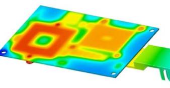
This ground-breaking technology performs structural, thermal, and modal analysis on 3D CAD designs in seconds. No more back and forth; no separate environments. Created especially for design engineers, the analysis updates dynamically in real-time as you edit, create new features, or change properties.
New in Creo Simulation Live: Fluid Flow Simulation
Creo 7.0 introduces Fluid Flow Simulation to Creo Simulation Live. Built specifically for designers, the software gives you real time Fluid Flow Simulation capabilities directly integrated within your Creo environment. Creo 7.0 also introduces UI enhancements and improved workflows to increase your productivity.
Analysis Capabilities
- Linear Static Structural Analysis
- Static Structural Analysis with Small Displacement Contact
- Modal Structural Analysis
- Linear Buckling Structural Analysis
- Linear Steady State Thermal Analysis
- FEM mode: Use of NASTRAN solver
- Linear Static Structural Analysis
- Modal Structural Analysis
- FEM mode: Use of ANSYS solver
- Linear Static Structural Analysis
- Modal Structural Analysis
- Linear Steady State Thermal Analysis
| Capability | Creo Simulation Live | Creo Design Essentials | Creo Simulation Extension | Creo Advanced Simulation Extension |
|---|---|---|---|---|
| Real-Time Simulation | ||||
| Finite Element Analysis for Parts and Assemblies | ||||
| Static Structural Analysis | ||||
| Finite Modeling Idealizations | ||||
| Automatic Meshing | ||||
| Results Display and Reporting | ||||
| Modal and Buckling Analysis | ||||
| Steady State Thermal Analysis | ||||
| Design Optimization | ||||
| Contact Analysiss | ||||
| Advanced Finite Element Idealizations | ||||
| Non-Linear materials and large deformation | ||||
| Dynamic and Pre-Stress Analysis | ||||
| Transient and non-linear thermal Analysis |
Creo Ansys Simulation
With Creo Ansys Simulation, PTC and Ansys put the power of gold-standard simulation at the fingertips of the design engineer. Creo Ansys Simulation offers high-fidelity, high accuracy simulation for design refinement and validation. Best of all, the capabilities do not require expert knowledge to use and are accessible via the familiar Creo user interface. You can analyze your model and quickly identify problem areas. Once you update the design, you can easily rerun the analysis, without recreating it.
Features and Benefits:
- Powered by Ansys, with high-fidelity, high-accuracy simulation for design refinement and validation
- Linear Static Structural Analysis, Modal Structural Analysis, and Steady State Thermal Analysis
- Multiple studies per simulation model
- Automatic mesh and contacts (advanced options for manual control)
- Support for masses, springs, shells, and beams
- Boundary conditions specified on geometry.
- Associativity with Creo Simulation Live Setup
Creo Simulation Live, Powered by Ansys
Structural Boundary Conditions

- Fixed Support
- Enforced Translations and Rotations (Optional - apply from a remote point)
- Planar, Cylindrical, Ball and Frictionless Constraints
- Force Load
- Specified in terms of total or per unit area
- Total load at a point
- Moment Load
- Pressure Load
- Bearing Load
- Gravity Load
- Centrifugal Loads specified by the angular velocity or angular acceleration of the structure
- Temperature Load
- Linear Acceleration Load
Thermal Boundary Conditions
- Boundary Conditions specified on geometry.
- Prescribed Temperature
- Convection Condition
- Radiation Condition
- Heat Flow
- Heat Flux
- Heat Generation
General Modeling Tools

- Units Manager - Commonly used units for all quantities available
- Creation of custom units and unit systems
- Creation of custom units and unit systems
- Results in user selected units
- Surface Regions
- Defined by sketch or curves
- Coordinate Systems
- History-based, associative, parametric features
- User defined Cartesian coordinate systems
- Typical metals and plastics included
- Storage of user defined materials
Meshing, Element Types and Idealizations

- Automated Physics-aware and part based meshing process
- Hexahedral and tetrahedral elements automatically created
- Mesh resolution slider bar to control fidelity in results
- Local mesh refinement
- Body, face and edge sizing supported
- Global mesh size options (all with respective size values)
- Curvature
- Proximity
- Fixed
- Shell definition and support
- Multiple beam sections and properties
- Beam releases
- General specification of Beam Section
- Orientation
- Beam release
- Constant Stiffness Springs
- 1D and 3D
- Torsional and longitudinal
- Optional Preload
- Fix to ground
- Point Masses
Connection

- Joints
- Geometry based definition (edges, points and surfaces)
- References to ground
- Multiple types
- Fixed, hinge, translational, slot, cylindrical, universal, spherical and planar
- Contact Interfaces
- Automatic or manual contact definition
- Surface-Surface Definition
- Bonded or no separation types
Results

- Basic and Advanced results
- Result Window Templates
- Full Results post-processing
- On full model or selected geometry
- Fringes, Contours, Iso-surfaces
- Large variety of contour plots
- Vector Plots
- Animation
- Simulation Probes
- At Point
- Maximum/Minimum/Average/Sum over Model
- Maximum/Minimum/Average/Sum over Selected Geometry
- Control over units
- Saved with results
- Simulation tree support
- Update results after new result definitions
- Simulation Query
- Active measuring based of legend selection
- Save option
- Launch Results in Auxiliary window
Process Tools

- Creo Ansys Model is an integral part of CAD model and fully supported by Windchill® (WC 12.1)
- Results optionally uploaded to Windchill and automatically associated to the model (WC 12.1)
- 4-Core parallel solution solver
- Export to Ansys Workbench/Mechanical
- Save APR format
- Archive that contains the model and simulation data